OCCAM Crossover Assembly Instructions
Tools Needed
- Hot Glue Gun
- Philips Screw Driver
- Soldering Iron, and Solder
-1/8" Drill Bit and Drill
- Download of scematic from FREE designs page of this web site
Parts Utilized From The Kit
-Crossover Board
- Speaker Wire
- 4 x 1" black screws (seen in picture)
- 4 x Nylon Spacers (seen in pictures)
- 3 x Black Zip Ties
- All Capacitors, Inductors, and Resistors in the Kit
Instructions
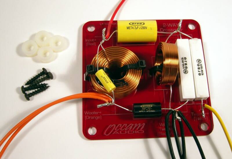
Following the Sticker Key found on the reverse side of the crossover, attach all crossover parts to the front of the crossover board as indicated by the Key. Use the supplied zip ties to attach the inductors, and hot glue to attach the other parts. The finished crossover board will look very much like the photo on the left. Using solder attach the wires to the positions described on the face of the crossover board. The actual value you use may vary from the photo on the left, but the final appearance will be similar. Once you finish the crossover, attach the crossover to the inside of the cabinet using the supplied screws and spacers. The spacers are there to lift the board off of the surface of the box. If you are building your own box, or if your kit does not have holes drilled out for this, you may need a drill and a 1/8" drill bit to drill 4 holes in the back of the speaker enclosure corresponding to the 4 holes in the crossover board. Attach the board and hook the speaker wires to the correct drivers and input cup.
Wiring diagram
- Yellow wire = Tweeter positive wire
- Orange wire = Woofer positive wire
- Red wire = Input cup positive wire
-Black Wire = Input Cup negative, Woofer negative, and tweeter Negative.
Click Picture to enlarge
OCCAM Kit A Instructions
Tools Needed
- Table Saw (or have someone cut the appropriate boards for you)
- Philips Screw Driver
- Brad Nailer (optional)
- Wood Glue
- 1/4" Drill Bit
-1/8" Drill Bit
- Drill
- Box diagram from the FREE designs page ot this website
Parts Utilised from the Kit
-Baffle
Instructions
Using the downloaded box construction diagram, cut the boards for the sides, top and bottom, and the back of the enclosure. The boards all need to be glued and fastened together. there are many ways to do this depending on the tools you have at hand. Below are a two different methods for doing this.
Nailing the enclosure together
This is the easiest method for assembling the box. You simply glue the boards together and tack the boards with a pneumatic brad nailer to hold them until the glue dries. Typically you would start with two boards and run a glue line where they meet, and tack them together to dry. Continue this until the box is finished.
Screwing the enclosure together
This method is usually only used if you do not have access to a nailer, or if you are a stickler for strength. Like the nailed process you will use a glue line where two boards meet, but instead of nailing the boards together you will use screws to hold the boards whitle the glue dries. The first step is to pre drill all the holes for the screws prior to gluing. It is recommended that you counter sink the screws so when you are done the screw heads are flush with the surface (or lower) so you can finish the speakers and not have screw head in your way.
A few tips
Cutting the boards exactly will greatly help with getting the box together with minimal sanding or filling. Do not cut your boards until you receive your baffle in the mail. The reason for this is that the baffle can be used as a guide to cutting the other boards to ensure they are all identical. If you do not get the box perfect, you can sand the areas that stick out, and you can fill any gaps with spackle. If you are going to finish it with either paint or veneer you will be able to hide many of the small problems you may run into. You can gleam some information on finishing the enclosure by looking at the Kit B Paint and Veneer instructions below.
OCCAM Kit B Paint Instructions
Tools Needed
1/8" or 1/4" roundover router bit and router (optional)
- Spackle
- Spreader or Putty Knife
- 240 Grit sand paper
- 400 Grit sand paper
- Sanding Sealer
- Paint
Parts Utilized from the Kit
-Baffle
- Interface
- Body
Instructions
If you choose to have rounded corners use your choice of radius bits, and router to round the edges of the front of the baffle, and the back of the body. I would not recommend radiusing the interface, instead you can use the 240 grit sand paper to soften the sharp edges. Using the spreader apply spackle to all open pored edges of the baffle, interface, and body. Spackle any screw holes on the back of the body that are not used on your model. This will typically be 4 holes spaced wider than the supplied input cup. These holes are there if someone decided to use an OCCAM 4" aluminum input plate instead of the plastic input cup supplied in the kits. Wait for spackle to dry according to the spackle instructions. Use the 240 grit sandpaper to sand the spackle down so it leaves the open pores of the MDF filled, and smooth. Once you are satisfied with this (it may take 2 coats of spackle) proceed to coat the parts with sanding sealer. Sanding sealer will seal the MDF so your paint will not soak into the MDF. Once the Sanding Sealer dries, sand it with 400 grit sand paper. Sand enough so that the surfaces are smooth to the touch but not enough to sand through the sealer. This may take two coats to accomplish. After this apply your choice of paint.
If you desire an automotive finish, I would recommend taking your parts to an autobody shop for assistance. The coatings and filler they use is hazardous and needs to be used by trained professionals.
OCCAM Final Assembly instructions
Tools Needed
- Phillips Screw Driver
Parts Utilised from the Kit
- 5/32 Allen Wrench
- Finished Crossover board (from above)
- Finished Baffle, Interface, and Body
- Grill
-Drivers
- input Cup
- Aperiodic Vent (if supplied)
Instructions
OCCAM Kit B Veneer Instructions
Tools Needed
- Veneer
- Glue
- Clothes Iron
- Razor Blade
- 1/4" Trim Router Bit (seen in picture on left)
- Stain (optional)
-Glaze (optional)
- Sanding Sealer
- Clear Top Coat (lacquer, polyurethane, varnish etc...)
- 240 Grit Sand Paper
- 400 Grit Sand Paper
Parts Utilised from the Kit
- Baffle
- Body
Instructions
Cut veneer into pieces slighlty larger than the surface you are going to attach them to. Follow the instructions below to attach the veneer to the surface. The video clip shows the wood glue method.
Wood Glue
Using wood glue, coat the surface you are going to veneer, make sure you use ample wood glue, and use a spreader or roller to make an even layer of glue. Place the veneer on tthe surface, and use a common clothes iron tto add heat and pressure to the surface, and evaporate the moisture in teh glue makeing the glue dry and hold teh veneer in place. Use either the trim bit or a razor blade to trim the extra veneer that overlaps on all sides. Continue this with all surfaces.
Iron On PVA glue
Very siimilar to wood glue except that you coat each surface with 2 coats of glue, wait for the surfaces to dry, and use a iron to melt the two together.
Contact adhesive
Use contact adhesive (preferrable one made for veneering) and coat back of veneer, and surface to be veneered. Once the contact adhesive becomes tacky, place teh veneev on the surface you are veneering, and apply pressure. A J roller or other pressure roller may be useful for this.
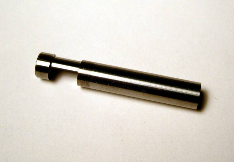
WhiteSide Part# SC28C 1/4" Trim Bit
Click Picture to enlarge
NOTE
The instructional DVD shows a 1/4" panel used to seperate the baffle from the back box while veneering. The kits do not come with this panel, but instead come with 1/4" thick wooden spacers.